Time Squared – Word Clock
December 5, 2010 12 Comments
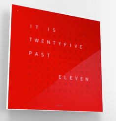
A company in Germany sells absolutely stunning time pieces that attract oohs and ahhs from everyone who sees them. They are called the ‘Qlock Two’. If you are like me and crave balance and symmetry, the Clock Two will not disappoint. Unfortunately they are not yet available in the United States, and at $1500 a piece, it is unlikely that they would be easy to come by, even if they were sold here. Now that is a problem, because I really want one.
Update: The code is now hosted on github
Note that there are two branches, Master and Arduino Uno
If you are using the newer Adruino Uno board (It will say uno on it) Make sure you check out the code from the Arduino Uno Branch.
https://github.com/spudstud/TimeSquared
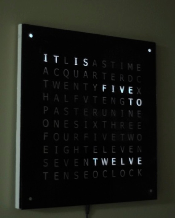
With the college semester coming to a close, I decided to do something about my predicament of wanting something I couldn’t have. About 3 weeks and $85 later the ‘Time Squared’ was born.
Technical Features
114 white led’s wired in a matrix
Atmega 328 Microprocessor @ 16Mhz
2 Led Drivers (Maxim 7219)
Atomic Clock Radio to automatically update time WWVB
1307 IC programable Real Time Clock
Light Sensor – Automatically adjusts to room brightness
Touch Sensors Switch modes (on/off, seconds, manual update)
Plexiglass front with black vinyl sticker cutout
On to Construction
The real Qlock Two is made from high quality molded plastics. Since I am a student and make minimal money, I settled for a steel back and wood frame.
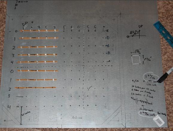
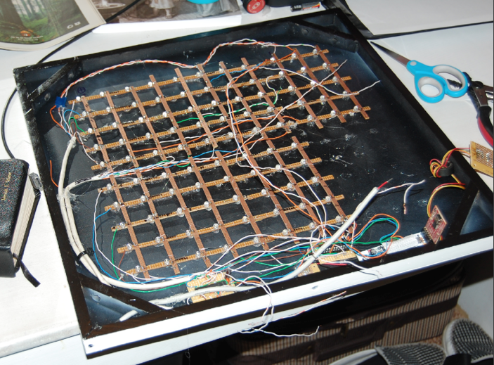
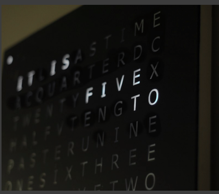
The dimensions are 18 x 18 inches square. There are 11 Columns and 10 rows of lights plus 4 leds in the corner totaling 114 leds in total. The placement of the center of each light was measured on an Adobe Illustrator file of the letter layouts. Luckily I was not the first person to do this project so I used RuddBurger’s pre made file here (it’s in german)
The L.E.D.s where soldered to VeroBoard. I bought an 11 X 6 Inch board and tediously cut it into strips using a jewelry saw. This part was by far the most grueling part of the whole project. I could have bought smaller strips that would require less cutting, but I had to save every penny I could on this project.
In case you are wondering, veroboard is a type of circuit prototyping silica that has single lines of copper that run one direction of the board. I bought mine on ebay for less than $10.
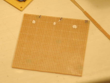
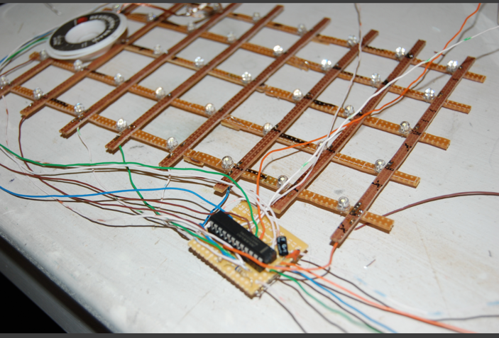
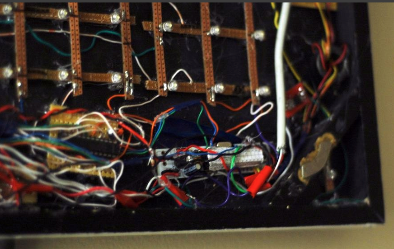
The led’s were then soldered to the veroboard. Since the final circuit would be wired in a matrix where the – goes along the horizontal line and the + goes along the vertical, I cut the copper next to every – lead isolating them from their neighbors. It will become more clear why I did this later on.
Each hole in the vero board is exactly 1mm apart. Since my measurements didn’t line up exactly with the veroboard, some leds are 12mm apart and others are 13mm apart. In the picture the horizontal are the negative and the vertical strips are the positive. I eventually realized that by leaving the + leg on the led’s I would need less wire when I hooked up the vertical strips.
one six-foot strip of soft “base board” wood was cut at 45 degree angles to make a perfect square 18 inch frame. Scrap wood was then used to reenforce the corners. Ace hardware made the four 45 degree angle cuts for me on their circular saw. Despite asking for a deal they still charged me .50 cense a cut! ( I told you that I am broke!) I cut the inside supports by myself trying to save two bucks, but realized that 45 degree angles are very difficult do make with a hand saw. Don’t be cheep like me, cut them right. (Also I highly recommend not taking on projects while you are a student in college).
Getting the 4 corners to line up at exactly 90 degrees was much more difficult than I would have thought.
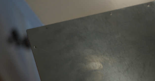
A center punch, 1/16 if an inch drill bit and the smallest nails I could find firmly attached the wood to the metal.
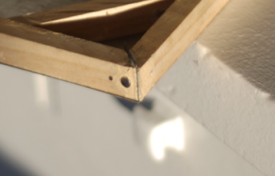
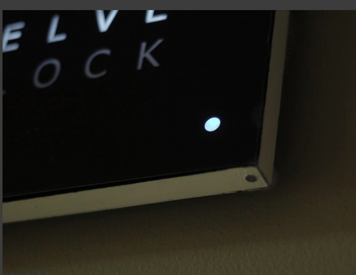
I went one step further and put a big fat nail in the bottom two corners These would be the touch sensitive buttons. Rather than pysical buttons, a circuit attached to these metal nails will respond simply by touching them with anything that holds a charge (e.g. your skin). I originally tried putting strips of metal in the corner, but found they were too sharp and too difficult to stay in place. If you look really close at this picture, you may still be able to see the metal strip.
A broken printer sacrificed it’s usb port. We will forever thank you good printer. The hole in the wood is for the light sensor.
The led driver (maximum 7219) is hooked up to one section of the led matrix. This chip receives a simple binary number and turns on that number in the matrix for 1/600 of a second. The reasoning is; no two led’s can be turned on in the same row or column at the same time, since it would light up every led in between them. To the human eye the leds appear to be on constantly, but really are refreshing extremely quickly like a CRT Television. This is the part of the project that took some research. The 7219 needs a capacitor and a resistor. The resistor must be very carefully calculated depending on how many led’s you have and how many milliamps they are. A great tutorial on using this chip can be found at these links;
7219 Daisy Chaining * My design does NOT use daisy chaining.
7219 Vin Marshal Tutorial Thanks vin marshal. Most of my code was forked from his work.
Black acrylic paint on the inside and white on the outside with a protective clear coat. Spray paint gave less than optimal results. A good old fashion brush works best.
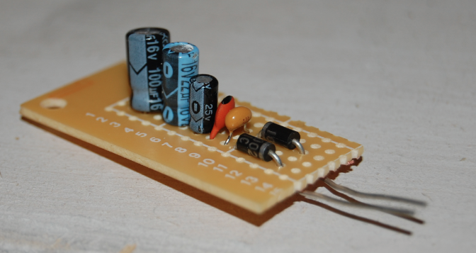
The usb port provided a steady 5 volt supply, however in certain situations, ripple and tiny power dips caused funky results from the microprocessor. It was most noticeable when running the clock from a usb wall adaptor. To resolve the issue I added capacitors to the input to reduce any ripple that was coming in from the AC to DC conversion. The diodes weren’t necessary and I eventually removed them. From right to left, 0.1pf, 22pf, 10uf, 40uf, 100uf capacitors. I am not an electrical engineer so note that this setup is probably overkill. If you want to learn more about ripple check out spark fun’s tutorial here.
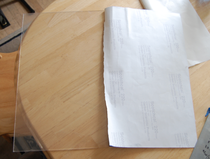
All parts in place and clear glass 18 x 18 panel being measured.
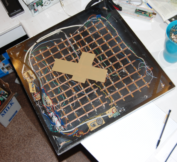
I originally started with 3/16” glass because it was much more scratch resistant and attracts less dust. Due to the fact that I was unable to get a perfectly square sheet and glass is heavy, I switched to 1/8” plexiglass.
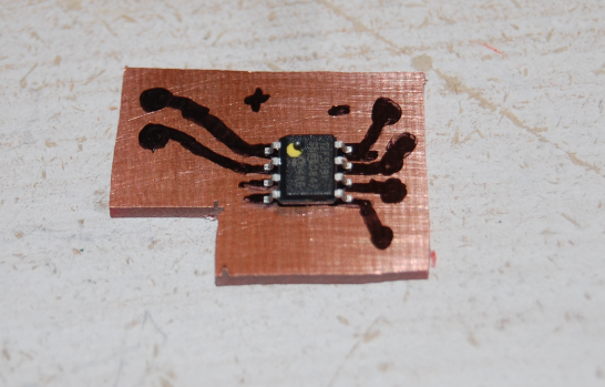
A custom circuit board for the touch sensor IC. A full tutorial on interfacing a touch sensor with an Arduino can be found on my blog here.
The plexiglass is attached to the frame with magnets so that it is easily changeable. I shopped around for a long online trying to find cheap super powerful thin magnets, but couldn’t find anything I liked. I realized that hard drive magnets are super strong, free and very thin. I routed out the wood and put the magnet in the wood with epoxy. Not very pretty but works great.
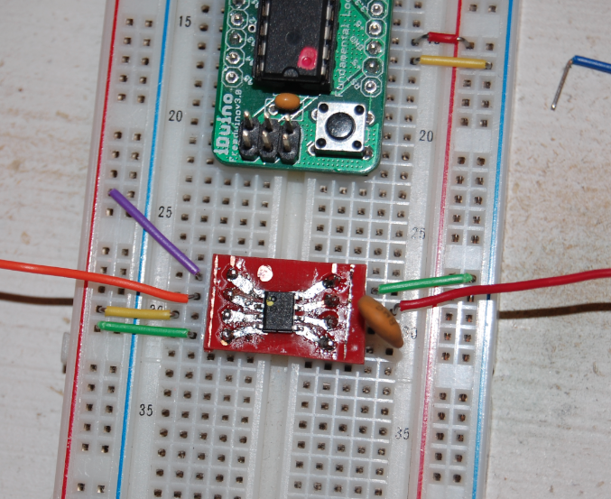
A picture of the Atomic Clock Module. Thanks to vinMarshal for help with the coding here. You can see his implementation here. I wrote a full arduino & WWVB (atomic clock) tutorial on my blog here.
Below it is the 1307 Real Time Clock. It is very easy to implement with an arduino since the libraries are very well documented. Simply send it the hour, minute, seconds, day and month and it will keep ticking as long as it has power. A backup battery prevents it from loosing the correct time. The clock is accurate to several minutes per year. I considered using the more accurate yet more expensive ChronoDot but since it has an atomic radio, the time is synchronized to the second with the Atomic Clock in Colorado every day.
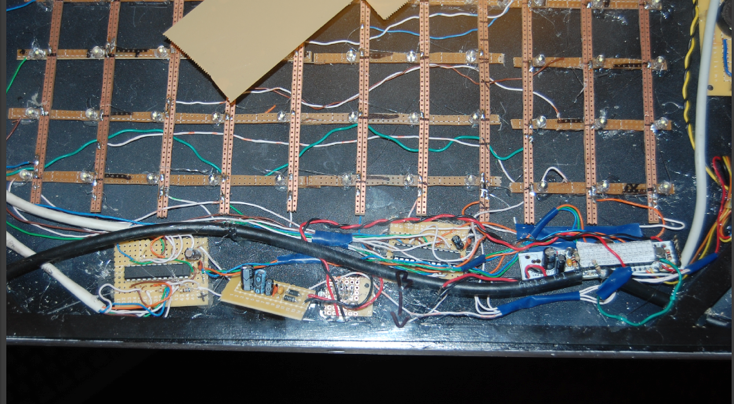
Do not use old solid core networking cable. It will make your life miserable. Instead I recommend you use good stranded core wire.
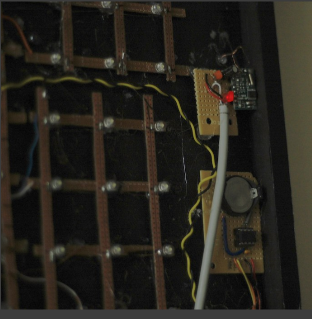
Below you can see the 7219 on the left, a RBB arduino in the center, and a red touch sensor dangling to the right.
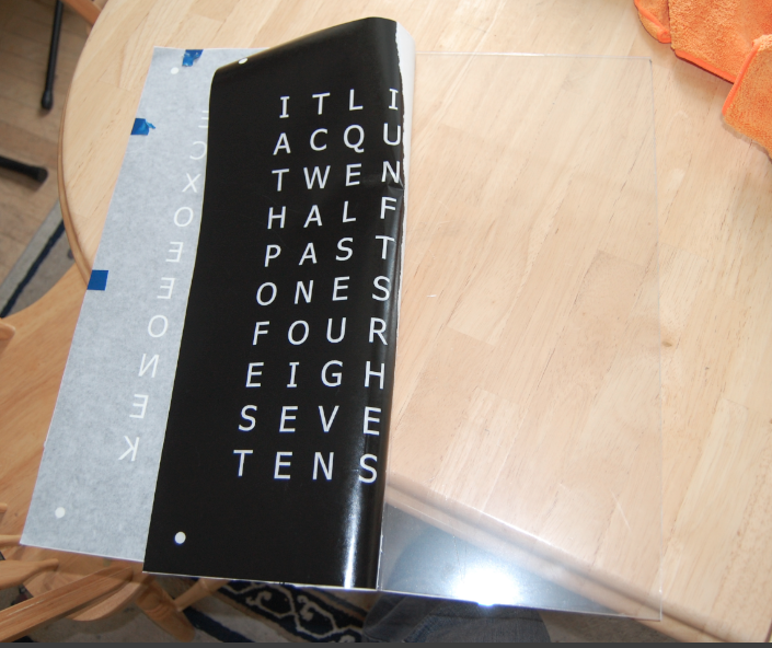
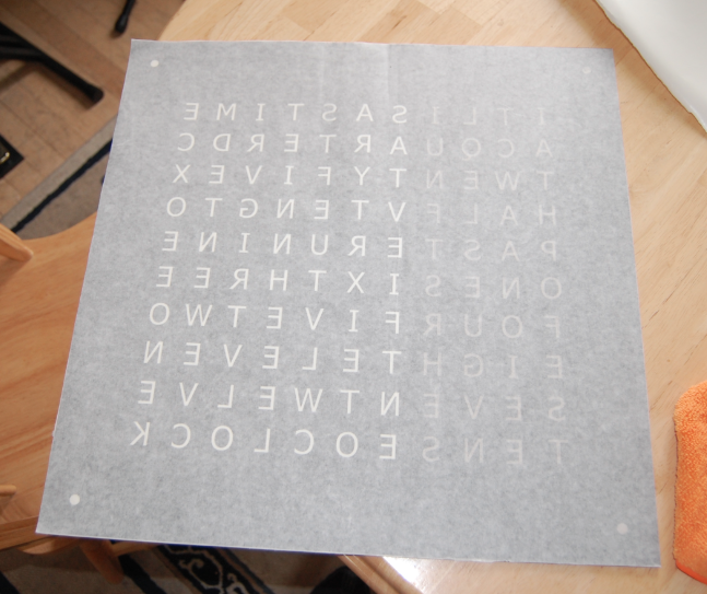
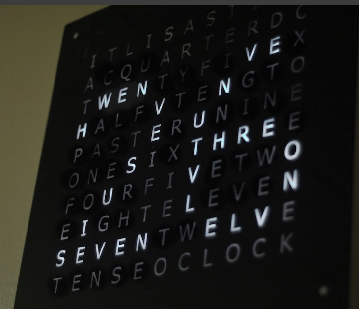
The black face was done with a vinyl sticker cut out and stuck to a piece of plexiglass. The sticker was applied to the inside of the plexiglass giving it a glossy look. Some have wondered about bubbles forming on the inside. When I first applied the sticker, there were a lot of bubbles despite my best effort to avoid them. Luckily they disappeared on there own after a couple of days. If I were to do this part over again I would have put some water with a drop of baby shampoo in a spray bottle and wetted the glass first. That makes any bubbles that do form very easy to squish out with a credit card.
Feel free to use my illustrator file here.
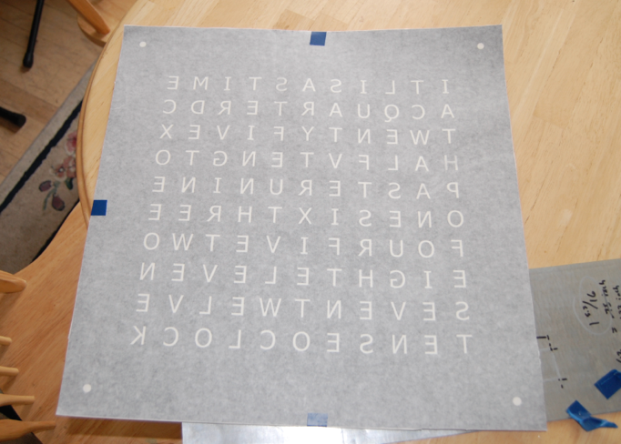
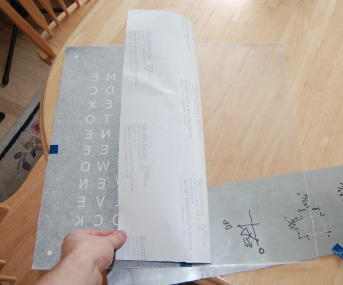
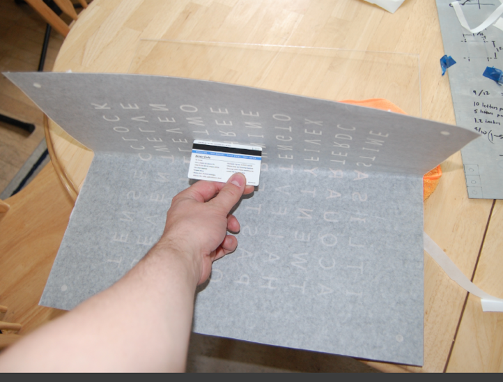
The best way I have found to attach stickers to a large object is to tape it down with the wax paper still attached. Then lift up 1/2 of the sticker. Remove the wax paper and carefully apply while removing all the bubbles with a credit card. Once the first half is in place, lift the other half of the sticker up and repeat. Take a look at this video of applying a sticker to a laptop to get a better idea of how it is done.
http://www.youtube.com/v/hJV1qIcWyio?fs=1&hl=en_US
I had more air bubbles than I would have liked. The next time I would probably use water with a tiny bit of baby shampoo to aid in the application process. Luckily about 95% of them went away on there own over the next few days.
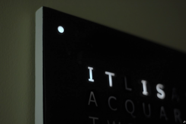
To help diffuse the light, I left the white backing on the sticker. It gave the letters a semitransparent white look and made the letters really pop.
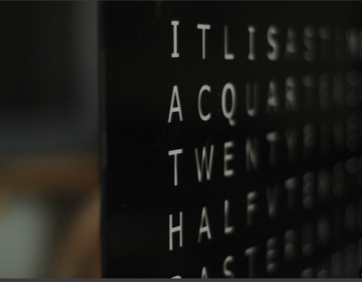
I considered making individual baffles to prevent the light from one letter from leaking into the neighboring letters. This turned out to not be necessary since the light bleed is less than expected.
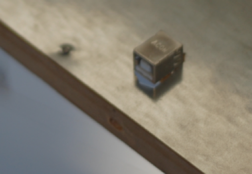
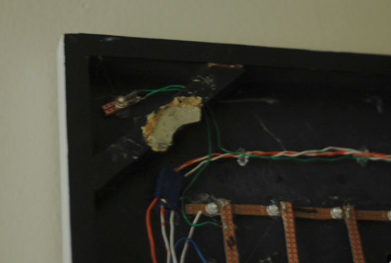
A photo of the corner and the metal nail acting as a touch sensor. The white paint was protected with a clear coat. All paint had to be removed from the metal touch sensor for reliable readings.
26 Seconds.
Other Resources
Inspiration
http://www.flickr.com/photos/19203306@N00/sets/72157622998814956/
http://blog.makezine.com/archive/2009/11/qlocktwo_remake.html
Illustrator File
http://crashdummy.nl/shizzle/qlocktwo_front_3372.eps
Light Sensors
http://www.instructables.com/id/Photocell-tutorial/
I welcome feedback and comments to help improve the quality of my posts. Have something on your mind? Let me know.

Pingback: Open Source Hardware? « Spencer's Technical Diaries
can I buy one? Very popular pic
Thanks for the nice words.
I have seriously considered mass producing them, however there is a trade off between quality and price that I just can’t seem to break.
Either they would be precision made with aluminum and plastic, but they would cost $500, or I could make them cheaply for about $175 but they would be held together with glue and tape and would not be very sturdy.
I am working on releasing the schematics and code so that others can copy what I have done.
Perhaps I will make kits with the electronics complete, but leave the woodwork and glass unto someone with more skills in that area.
I am open to input what you think would be best.
Can i know where did you have the vinyl made?
The company that referred me to the person who made it is here:
http://maps.google.com/maps?rls=en&oe=UTF-8&um=1&ie=UTF-8&q=rexburg+vinyl&fb=1&gl=us&hq=vinyl&hnear=0x53540a4b807a98b1:0x4a49d8d1d2181c73,Rexburg,+ID&ei=LPDbTtKiIcSsiQLR1K2FCg&sa=X&oi=local_group&ct=image&ved=0CAYQtgM
They were very helpful, though did not have the black material that I wanted. They were in communication with a person in Salt Lake City who did the actual cutting. I paid about $30 for it. With tax and shipping.
Anyone who has a plotter should be able to do it for you.
Also try
Sign Pro
Signature Signs
I have worked with these companies in different projects, and have been happy with their results.
Realy liking your work here, did you ever decide wether or not to produce them or the circuirty?
I am at a point in my life where I can return attention to the Time Squared. I am redesigning the circuitry to make it modular, and most importantly, I am using a single sheet of plywood with holes drilled in it instead of the matrix of vero board for the LEDs. It will be at least a month, but revision 2.0 is on its way.
Hello Spencer,
Just to compliment your article about your Word Clock.
I’m in a the process of gathering all the bits required to build one as time permits.
Just a quick question if you don’t mind. I have a couple of ATmel AT42QT1011 touch sensors lying around, and I plan to use them in my word clock. I think that they should be very similar in terms of functionality to the one you are using. Do you know if there is any library required to make them work correctly? (to differentiate the “sense” of a (quick) touch and/or a long press…)?
Thanks
Luís
Glad to hear that you like the article. I am currently in the process of making version 2.0. I threw out the vero board and drilled holes in thin plyboard instead. I am also rewriting the software from scratch because it had some bugs.
https://github.com/spudstud/TimeSquared/tree/Revision2.0
To answer your question about the touch sensors; You don’t need any special library. They behave exactly like a push button. I used the principles mentioned below to allow for “push and hold” functionality”
http://arduino.cc/forum/index.php/topic,42489.0.html
I’d love to see how yours turns out.
I already have an 475 x 475 MDF wooden panel (mechanicaly) drilled with 128 holes (for leds), the front template made wtih 3mm plexiglass and a vinyl sticker with many, many bubbles 😦 . (I have made the text in Portuguese and since the beginning, some months ago, my thinking was to have the corner leds to represent the minutes)
Now I will have to deal with the “problem” of the four corner leds. This gives a total of 132 (128+4) leds. Since each MAX 7221 can only handle 64 leds, so, I have to work this out. It seems a little overkill to place a third MAX for just 4 leds… Maybe I’ll connect these 4 leds to the ATmega328 directly….
Let’s see what I can get.
I will keep an eye on your website to watch your progresses to version 2 on software and hardware..
Thank you.
Hi Spuder!
Just to let you know that a few days ago I managed to get my workclock version working (http://goo.gl/DuQaLI)!
By now the adjustment process is made using a rotary encoder, but in the future my intention is to change that to two hidden capacitive buttons beneath the plexiglass.
The clockface is completely written in Portuguese so eventually you won’t understand what it is telling, but you get the idea.
Enjoy
This is fantastic, This looks very well done.